The movie of the website we did can be found at https://drive.google.com/drive/folders/0B3nHZddKz-rwa0xzYWZHellwRzg.
Some snapshots:


The movie of the website we did can be found at https://drive.google.com/drive/folders/0B3nHZddKz-rwa0xzYWZHellwRzg.
Some snapshots:
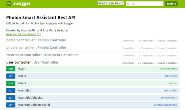
We continue with presenting the architecture of the application and the RestAPI.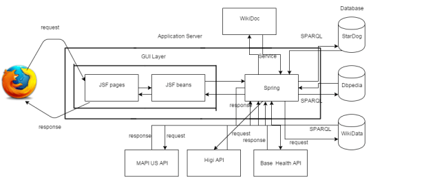
Last post about the diagrams…
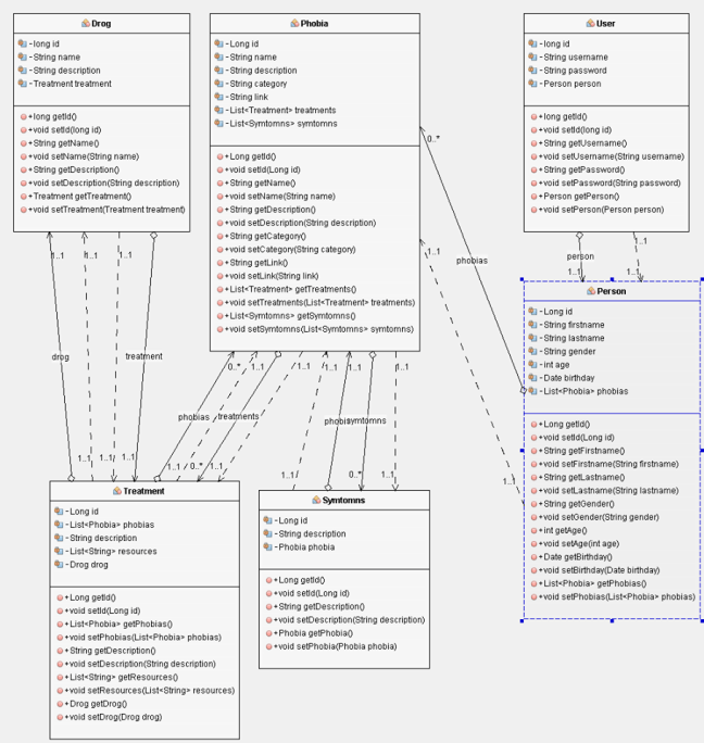
Class diagram
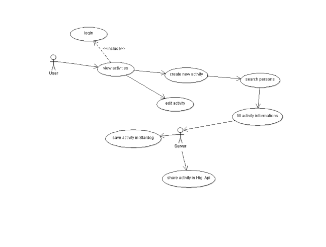
Use case Diagram for the Activity page
Another Use case diagram
As we said, we continued making these god forsaken diagrams. But first, we forgot to mention that what we used to make these.
ArgoUML is the leading open source UML modeling tool and includes support for all standard UML 1.4 diagrams. It runs on any Java platform and is available in ten languages.
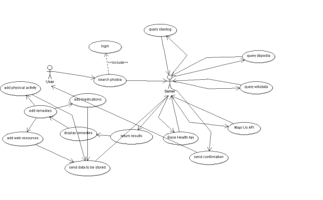
The Use Case Diagram
The purpose of use case diagram is to capture the dynamic aspect of a system.
Use case diagrams are used to gather the requirements of a system including internal and external influences. These requirements are mostly design requirements. So when a system is analyzed to gather its functionalities use cases are prepared and actors are identified. Now when the initial task is complete use case diagrams are modelled to present the outside view.
So in brief, the purposes of use case diagrams can be as follows:
The first Use Case Diagram for our application looks like this :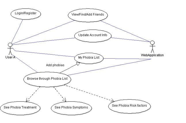
Next up: The class diagrams.
 UML stands for Unified Modeling Language which is used in object oriented software engineering. Although typically used in software engineering it is a rich language that can be used to model an application structures, behavior and even business processes.(go.to.source)
We prepare UML diagrams to understand a system in better and simple way. A single diagram is not enough to cover all aspects of the system. So UML defines various kinds of diagrams to cover most of the aspects of a system. You can also create your own set of diagrams to meet your requirements. Diagrams are generally made in an incremental and iterative way. (go.to.source)
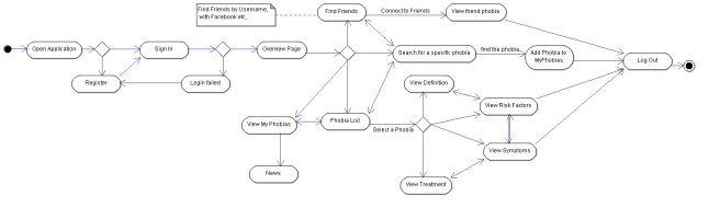
The Activity Diagram
An activity diagram is basically a flow chart to represent the flow form one activity to another activity. The activity can be described as an operation of the system.
So the control flow is drawn from one operation to another. This flow can be sequential, branched or concurrent. Activity diagrams deals with all type of flow control by using different elements like fork, join etc.
So the purposes can be described as:
The Activity Diagram for Phobia Smart Assistant
Up next: Use Case Diagram, to be continued ….

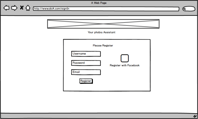
The first step is to create some mockups to see how our application will look like. Why? Mockups offers the same speed and rough feel as sketching with pencil, with the advantage of the digital medium: drag & drop to resize and rearrange elements, make changes without starting over, and your work is clear enough that you’ll make sense of them later.
So we installed Balsamiq and started the Trial version.
A very simple Register page
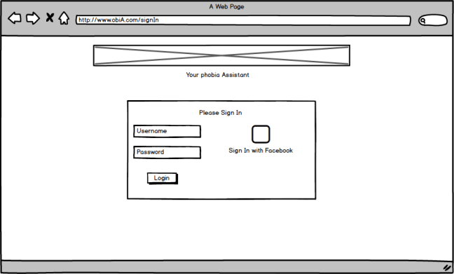
A very simple Login page
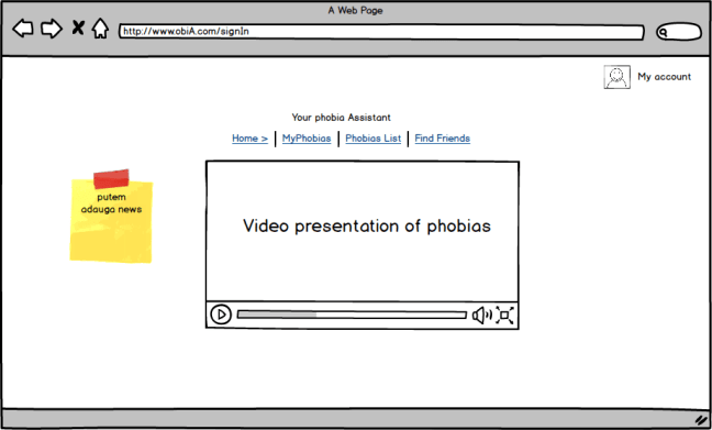
Home page
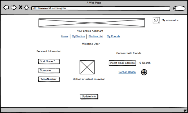
My account page
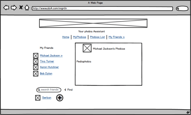
My friends page
The Phobia List page
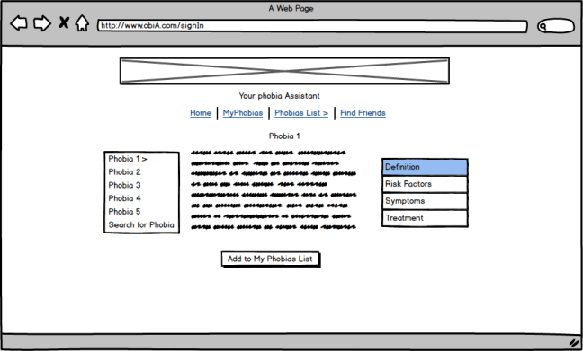
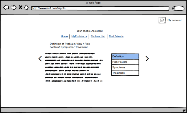
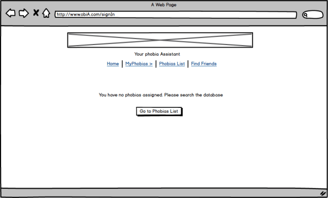
My Phobia pages
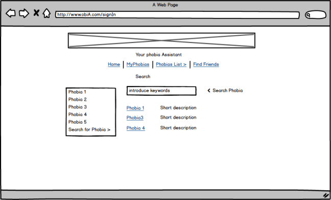
Search & add Phobias page
First draft… you don’t want to see the pre-first draft …
