 UML stands for Unified Modeling Language which is used in object oriented software engineering. Although typically used in software engineering it is a rich language that can be used to model an application structures, behavior and even business processes.(go.to.source)
We prepare UML diagrams to understand a system in better and simple way. A single diagram is not enough to cover all aspects of the system. So UML defines various kinds of diagrams to cover most of the aspects of a system. You can also create your own set of diagrams to meet your requirements. Diagrams are generally made in an incremental and iterative way. (go.to.source)
The Activity Diagram
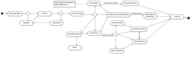
An activity diagram is basically a flow chart to represent the flow form one activity to another activity. The activity can be described as an operation of the system.
So the control flow is drawn from one operation to another. This flow can be sequential, branched or concurrent. Activity diagrams deals with all type of flow control by using different elements like fork, join etc.
So the purposes can be described as:
- Draw the activity flow of a system.
- Describe the sequence from one activity to another.
- Describe the parallel, branched and concurrent flow of the system. (go.to.source)
The Activity Diagram for Phobia Smart Assistant
Up next: Use Case Diagram, to be continued ….
